For about the last 3 years, the de-facto method of accessing physical components via the Raspberry Pi’s GPIO pins has been a Python library called RPi.GPIO, created by Ben Croston, who originally built it to control his beer brewing process. Despite its humble beginnings in a personal hobby project, it’s ended up being used in projects of all shapes and sizes by users around the world, and it has a big presence in education. In the Foundation, we’ve used it in many of our learning resources, and we use it at Picademy, our teacher training course.
Physical computing is one of the most engaging activities for teaching computing, and has plenty of scope in computational thinking, programming skills and logic as well as projects being more relevant to young people (think build a robot vs. sorting arbitrary lists).
Hello world
RPi.GPIO permits configuring pins as inputs or outputs, and then controlling output pins as high or low, and reading the state of input pins. Observe the following code, which could be considered the “hello world” of physical computing (flashing an LED):
import RPi.GPIO as GPIO
from time import sleep

GPIO.setmode(GPIO.BCM)
GPIO.setwarnings(False)

led = 17
GPIO.setup(led, GPIO.OUT)

while True:
    GPIO.output(led, GPIO.HIGH)
    sleep(1)
    GPIO.output(led, GPIO.LOW)
    sleep(1)
This “hello world” example is 11 lines long, and contains a number of oddities:
- Import renaming (
from RPi import GPIOalso works) - Set pin numbering to BCM mode (actual GPIO pin numbers vs. location on the board) – this is necessary, no default mode
- Set warnings off (the library prints warnings if you run a program twice because you already used that pin)
- Constants
GPIO.OUT,GPIO.HIGH,GPIO.LOW(TrueandFalsealso work for high and low) - Passing reference to pin number integer around
These are the sorts of things a teacher would probably skip over explaining, the way they would if they were teaching the “hello world” of Java. It doesn’t matter what public static void main(String[] args) means, you just have to write it.
While this is not an intuitive or Pythonic interface, it does allow many components to be used. Some, like LEDs, can be as simple as this. Others, like sensors, require clever manipulation of pin state reading to be useful. This makes a whole range of projects to be created, enabling users to create their application in Python, instead of having to use a lower level language.
The current state of affairs
RPi.GPIO is the de-facto standard, and its common use soon led to inclusion in the standard Raspbian image provided by the Foundation. It’s a Python module implemented in C (the project lives on sourceforge) and its features include:
- Configure pins as input or output
- Read inputs (high/low)
- Set outputs (high/low)
- Wait for edge (wait for input to go high/low)
- Pin event detection (callback on pin input state change)
- Software PWM (pulse-width modulation)
There’s a broad use of RPi.GPIO. It’s used in the Raspberry Pi Learning Resources, there are 23k code search results on github.com.
Sudo
In Raspbian Wheezy (Raspberry Pi optimised distro based on Debian Wheezy), root access was needed to access the GPIO pins. Users had to run Python files with sudo because the underlying code runs mmap() on /dev/mem . This meant that opening IDLE from the main menu did not allow GPIO code to be run, and IDLE had to be opened from the Terminal with sudo idle &. Since the release of Raspbian Jessie, the Pi user was given access to the GPIO pins via /dev/gpiomem, which makes a huge difference to the user experience, particularly for use in education or with beginners.
Motivation
I’ve been thinking for a while that there must be a way to make programming for physical computing more accessible. I gave a talk at the Cambridge Raspberry Jam in September, Build a Python API for Raspberry Pi Hardware, which included some basic code examples (wrapper classes around common RPi.GPIO code for LED, etc.) but mostly focused on packaging and distribution. The idea was to show add-on board manufacturers how to provide a Python module to go alongside their products, enabling users to make the most of it. This is something Pimoroni do very well.
After presenting the talk, I wondered if my example LED class, and similar abstraction classes would be useful to others. I thought of showing teachers how they can create such classes to make things easier for their students. Teachers do often say they don’t use Python because it’s too hard – but really it’s not Python that’s hard, it’s the modules they’re using making it more complicated than it needs to be, or the poorly written code they’re sourcing from the web.
The main problem with RPi.GPIO is that there’s too much boilerplate code needed to get started. The “hello world” LED program shouldn’t be 11 lines, and it shouldn’t contain anything too complex to explain to children. When you get to input devices, even simple ones like a push button, you’re forced to explain pull-up and pull-down circuits, a concept coupled with detecting falling and rising edges. I’m not saying it’s not an important concept, and that it should be taught at some point, but it shouldn’t be a barrier to entry. It just causes friction to anyone getting started. I’m talking about young people, perhaps Primary School or early Secondary, who have been programming with Scratch. The jump to Python shouldn’t be out of reach or they’ll never leave the comfort of drag-and-drop block programming.
Inspiration
Pimoroni have some great products to accompany the Raspberry Pi (check out their range of HATs) and they do a great service to their customers by providing Python modules for each of them (created by their software developer, Phil Howard). I’ve used many of their products, and the libraries and examples provided enable you to dive straight in, start prototyping and coding up an idea. There are other great modules available, such as picamera, the Python library for the official camera module, created by Dave Jones, allowing users to easily add photo and video functionality to their Python applications.
There’s also PyGame Zero, a zero boilerplate wrapper for PyGame created by Daniel Pope. If you haven’t seen it already, it’s well worth a try. Create an empty file, run it with pgzrun myfile.py and you have a game window. Add one line to change the background colour, add another couple to set the window height and width, add another and you have a playable character. It’s brilliantly simple to make a simple game and there’s no limit on where you can take it. The motivation for this was that some teachers at PyConUK 2014 said PyGame was too hard to teach with. I felt this needed doing for physical computing. It needed to be intended for teachers, children and beginners, but also be useful for hobbyists who knew their way around Python.
What do you think?
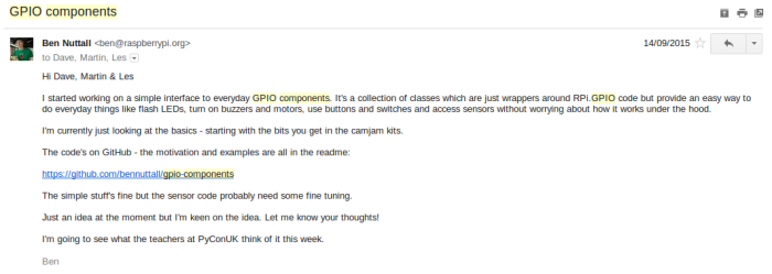
I threw my LED class example into a GitHub repo called gpio-abstraction (soon renamed gpio-components) and added some basic code. I demonstrated it to a few of my Foundation colleagues and it went down well. I showed Eben and he said “I’ll have one of those. Can you get it ready for the next Raspbian release?”. I said I wanted to test it out more and get feedback from some teachers, but probably have it ready for the release after. I then emailed some friends asking for their opinion:
I got a positive response from them all, and decided to press on. Dave (author of picamera) said he had a few minor observations:
 And he continued…
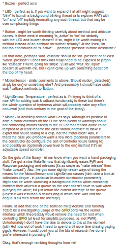
Then the next day…
As well as using GitHub issues for sourcing ideas feedback, I decided to also create a Google Doc to lower the barrier to entry for any teachers who wanted to contribute.
Name?
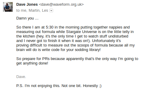
I posted an issue on GitHub asking for suggestions for a name:
I then had the idea to borrow the Zero from PyGame Zero, seeing as I was sharing the philosophy of removing boilerplate to make it easier for use in education:
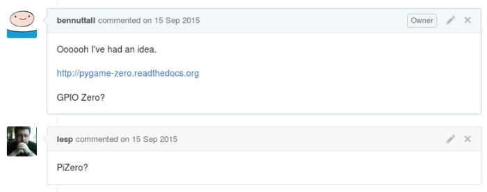
Les replied, suggesting “PiZero?”. Note the timing. This was before Raspberry Pi Zero was released, but obviously I was aware it was coming. In fact, it’s part of the reason I liked the idea of adding another Zero into the mix. I couldn’t really explain why calling the library Pi Zero wasn’t a good idea, but as Dave agreed GPIO Zero was a good name, I proceeded, renamed the repo and published an initial pre-release to PyPI.
The new hello world
Here’s my “hello world” program with GPIO Zero:
from gpiozero import LED
from time import sleep

led = LED(17)

while True:
    led.on()
    sleep(1)
    led.off()
    sleep(1)
or even:
from gpiozero import LED

led = LED(17)

led.blink()
More examples:
led = LED(17)

led.on()  # all on
led.off()  # all off
led.toggle()  # swap state of led
led.blink()  # on for 1 second, off for 1 second, continuously in the background
led.blink(on_time=2, off_time=2)  # change on/off time to 2 seconds
led.blink(n=10)  # stop blinking after 10 iterations
led.blink(n=10, background=False)  # 10 iterations, in the foreground so wait to complete before proceeding
PyConUK
My Foundation colleagues and I attended PyConUK, where we ran some workshops and sessions on the Education track, and I demonstrated it to some teachers who said it was exactly what they needed. I struggled to get any feedback other than “it’s great” – no constructive criticism, just general positivity. I also gave a physical computing talk on the main track, and mentioned by work-in-progress project GPIO Zero at the end. RPi.GPIO’s author Ben Croston happened to be sitting in the talk so I went over to ask what he thought at the end. He said he liked it and that he’d never intended RPi.GPIO to be an end-user library and expected someone else to provide a better API.
CamJam Kit 1
I started adding interfaces to all the components I could lay my hands on. I started with the CamJam EduKits as they contain simple everyday components. Kit 1 comprises a set of LEDs, a button and a buzzer. There are worksheets that come with the kit start with flashing the LEDs and programming a traffic lights sequence. There’s scope to add the button and buzzer for different road crossings, then go on to reaction games and morse code.
Button
Input devices in RPi.GPIO are rather obtuse. As well as configuring a pin as an input with GPIO.IN, you usually also provide a pull state: pull-up or pull-down. Pull-up means the circuit is wired to a GPIO pin and a ground pin, whereas pull-down means the circuit is wired to a 3V3 pin and a GPIO pin. So when a pulled-up button is not pressed, the GPIO pin state is high, and low when it is pressed. This is reversed for a button in a pull-down circuit.
To poll the input state of a pulled-up button using RPi.GPIO:
GPIO.setup(4, GPIO.IN, GPIO.PUD_UP)

while True:
    if not GPIO.input(4):
        print("Pressed")
The same code for a pulled-down button:
GPIO.setup(4, GPIO.IN, GPIO.PUD_UP)

while True:
    if GPIO.input(4):
        print("Pressed")
These two snippets of code do exactly the same thing for differently wired buttons, but require a logic shift. Alternatively, you can use if GPIO.input(4) == GPIO.LOW and if GPIO.input(4) == GPIO.HIGH but you still have the same issue. My instinct is to jump at the chance to avoid the GPIO constants and use Python’s Truth evaluator as it seems more natural.
However, in GPIO Zero, you create a Button object, which assumes the common pull-up circuit by default. Then to check its state, you access the is_active property. The alias is_pressed is provided for the Button class:
button = Button(4)

while True:
    if button.is_pressed:
        print("Pressed")
To use the pull-down alternative, you just provide pull_up=False in the init parameters:
button = Button(4, pull_up=False)

while True:
    if button.is_pressed:
        print("Pressed")
Note that the button.is_pressed code logic remains unchanged and is not coupled with the pull state.
Wait for edge
Another useful function in RPi.GPIO is wait_for_edge, which halts the program until a GPIO event is activated. For example:
GPIO.setup(4, GPIO.IN, GPIO.PUD_UP)

while True:
    GPIO.wait_for_edge(4, GPIO.FALLING)
    print("Pressed")
The edge needs to be the opposite direction of the pull state (normal state is high, and a falling edge indicates the button was pressed). The opposite case:
GPIO.setup(4, GPIO.IN, GPIO.PUD_DOWN)

while True:
    GPIO.wait_for_edge(4, GPIO.RISING)
    print("Pressed")
In GPIO Zero, the pull-up case:
button = Button(4)

while True:
    button.wait_for_press()
    print("Pressed")
And the pull-down case:
button = Button(4, pull_up=False)

while True:
    button.wait_for_press()
    print("Pressed")
Again, there’s no need for the configuration and edge type to be coupled, so it’s abstracted away.
Callbacks
Another very useful feature of RPi.GPIO is event detection with callbacks:
GPIO.setup(4, GPIO.IN, GPIO.PUD_UP)

def pressed(pin):
    print("Pressed")

GPIO.add_event_detection(4, GPIO.FALLING, pressed)
This means whenever the button is pressed, the pressed function will be run.
The equivalent in GPIO Zero is passing in a function to the when_activated property (the Button alias is when_pressed):
button = Button(4)

def pressed():
    print("Pressed")

button.when_pressed = pressed
Note that in the RPi.GPIO example, the function was declared to take a pin argument which was unused. The pin number is always passed in to the callback function. This can be used to determine which pin caused the callback to run:
GPIO.setup(4, GPIO.IN, GPIO.PUD_UP)

def pressed(pin):
    print("Pin %s pressed" % pin)

GPIO.add_event_detection(4, GPIO.FALLING, pressed)
In GPIO Zero, no argument is necessary, but if the function takes one, the device object will be passed in, which can be inspected for its pin number:
button = Button(4)

def pressed(button):
    print("Pin %s pressed" % button.pin)

button.when_pressed = pressed
As well as custom functions, you can also pass another object’s method in as the callback:
from gpiozero import LED, Button

led = LED(17)
button = Button(4)

button.when_pressed = led.on
button.when_released = led.off
This example uses both the when_pressed (when_activated) and when_released (when_deactivated) properties to allow a LED to be lit when the button is pressed, and unlit when released.
PWM
Another obtuse but useful feature of RPi.GPIO is PWM (pulse-width modulation). Oddly, unlike with regular in/out pins, this involves some object-oriented code:
GPIO.setup(17, GPIO.OUT)

p = GPIO.PWM(17, 100)  # pin 17, frequency 100Hz

p.start(0)  # initial duty cycle
for i in range(101):
    p.ChangeDutyCycle(i)
    sleep(0.01)
This code would fade the brightness of an LED from 0 to 100%.
We decided to keep the LED class in its simple on/off form, and provide a separate PWMLED class for configurable brightness. The PWMLED interface provides the standard on() and off() methods but also provides a value property:
led = PWMLED(17)

for i in range(101):
    led.value = i / 100
    sleep(0.01)
Full colour LED
Another common component is the RGB LED: three regular LEDs inside one casing. With a binary interface to each LED, you can only create seven different colours by combining the three primary colours. However, with PWM to control the brightness of each, you can combine them in different ways. It’s not going to be particularly accurate but it does give you much more flexibility:
led = RGBLED(red=2, green=2, blue=4)

led.red.on()  # full red
led.color = (1, 0, 1)  # purple
led.blue = 0.3  # dim the blue value to 0.3, now (1, 0, 0.3)
Boards and collections
Traffic Lights
lights = TrafficLights(9, 10, 11)

lights.on()  # all on
lights.off()  # all off
lights.red.on()  # red on
lights.toggle()  # swap state of all lights
lights.blink()  # blink all lights together
Traffic HAT
The Traffic HAT is a neat add-on board using the official Raspberry Pi HAT specification, and handily provides three LEDs (in traffic light colours), a button and a buzzer. I created an interface to this board, partly as a proof-of-concept, partly as a demo to other add-on board manufacturers to show how it can be done (and why it’s useful):
th = TrafficHat()

th.on()  # all lights and buzzer on
th.off()  # all lights and buzzer off
th.lights.on()  # all lights on
th.lights.off()  # all lights off
th.lights.red.on()  # red light on
th.lights.toggle()  # swap state of all lights
th.lights.blink()  # blink all lights together
th.button.when_pressed = th.on
th.button.when_released = th.off
Note that this class does not need initialising with pin numbers as they’re already known.
An optional feature of this class is enabling PWM on the LEDs:
th = TrafficHat(pwm=True)

th.lights.red.value = 0.2
th.lights.amber.value = 0.4
th.lights.green.value = 0.8
CamJam Kit 2 – Sensors
The second CamJam EduKit contains a Motion Sensor, Light Sensor and Temperature Sensor, broadening the scope for hobby projects into things like security alarms, darkness triggered lights, temperature indicator lights and such.
PIR Motion Sensor
The PIR (passive infra-red) motion sensor is a commonly used component and many people find them rather difficult to deal with in software. Because they’re digital and only yield high or low, you’d think you’d have to detect the value changing with one of the edge detection methods, but they’re very jittery so you end up writing functions to check the value ten times in a second and assuming motion if more than half are high. For example, in RPi.GPIO:
def check_motion():
    sleep(0.1)
    return GPIO.input(14)

while True:
    if sum(check_motion() for i in range(10)) > 5:
        print("Motion detected")
We implemented something similar to this, but the queue fills automatically in the background, so you can check the motion state at any point, without having to wait. It’s also configurable so you can specify the queue length, the threshold and more (if you want to). We picked some sensible defaults that seem to work reasonably well, and of course the API exposed makes it really straightforward to use:
pir = MotionSensor(4)
led = LED(17)

pir.wait_for_motion()  # alias for wait_for_active
pir.wait_for_no_motion()  # alias for wait_for_inactive
pir.when_motion = led.on  # alias for when_activated
pir.when_no_motion = led.off  # alias for when_deactivated
pir.motion_detected  # alias for is_active
Light Sensor
Similarly, the LightSensor interface:
sensor = LightSensor(5)
led = LED(17)

sensor.wait_for_light()  # alias for wait_for_active
sensor.wait_for_dark()  # alias for wait_for_inactive
sensor.when_dark = led.on  # alias for when_deactivated
sensor.when_light = led.off  # alias for when_activated
sensor.light_detected  # alias for is_active
Temperature Sensor
There’s already a Python library for the one-wire temperature sensor, and initially I imported it and added a couple of aliases to make it more like the other interfaces. However, as the library developed, it became less like the others, and we decided to leave it out for the major release. We intend to bring it back in at some point in a way that will be purely compatible with other GPIO Zero component interfaces.
CamJam Kit 3 – Robot
By this time, CamJam kit 3 had been announced. I’d heard it was going to be a build-your-own-robot kit.
Motor
Around this time I had already been playing with some simple motors using a motor controller board on the Pi. The way a motor works is you control two output pins: if one is high and the other low, it drives in one direction; if swapped, it goes the other way. I wrapped these steps in the obvious method names and we had a Motor class that worked pretty much as simply as the LED class:
motor = Motor(forward=17, backward=18)

motor.forward()  # drive the motor forward
motor.backward()  # drive the motor backward
motor.reverse()  # reverse direction of the motor
motor.stop()  # stop the motor
Robot
Stick two motors on a chassis and you have yourself a robot:
robot = Robot(left=(17, 18), right=(22, 23))

robot.forward()  # drive the robot forward
robot.backward()  # drive the robot backward
robot.left()  # drive the robot left
robot.right()  # drive the robot right
robot.reverse()  # reverse direction of the robot
robot.stop()  # stop the robot
I also provided pre-configured robot interfaces for some common motor controller boards to save users having to configure the pin combinations:
rtk = RyanteckRobot()
cmkr = CamJamKitRobot()
Analogue
The Raspberry Pi has no native analogue pins. However, by wiring up an ADC (analogue-to-digital converter), you can connect up a number of analogue signal channels.
MCP3008
A while ago I was introduced to the MCP3008 ADC for a project involving a bunch of linear and rotary potentiometers. I found some useful code written by Martin O’Hanlon, who created a wrapper class around some SpiDev code, providing easy access to data values. He kindly contributed it to GPIO Zero and we normalised its values from 0-1023 to 0-1. I started playing with it. The simplest example is a loop polling the value property while spinning a potentiometer around:
pot = MCP3008()

while True:
    print(pot.value)
I then added an LED and used the potentiometer to dial up and down the brightness, since both are on a scale from 0-1:
led = PWMLED(2)
pot = MCP3008()

while True:
    led.value = pot.value
Note there are 8 channels on the MCP3008, and the default channel is 0. Use MCP3008(channel=n) to specify another channel. The Pi also allows multiple ADCs to be connected, so you can also provide a non-zero device number with MCP3008(device=d, channel=c).
Then I wired up three potentiometers to an RGB LED to the same effect:
led = RGBLED(2, 3, 4)
red_pot = MCP3008(channel=0)
green_pot = MCP3008(channel=1)
blue_pot = MCP3008(channel=2)

while True:
    led.red = red_pot.value
    led.green = green_pot.value
    led.blue = blue_pot.value
#76 while True: led.red = pot.value
Then I thought that this must be a common use case – that you’d often want to connect the value of one input device directly to an output device, and wondered if there could be a way to do this automatically. As I thought this, it seemed stupid in my head. But it would be handy to not have to loop it over constantly updating, hogging up the program so nothing else can happen, or making it hard to update because you’re trying to do something else. I wrote an issue on GitHub explaining the idea, and asking if anything could be possible. I almost didn’t submit the issue as I thought it was bound to be impossible:
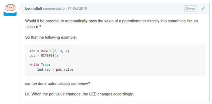
I was thrilled to see Dave’s reply:
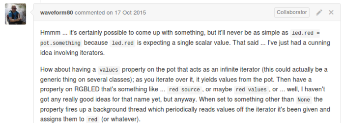
A few comments of discussion later and he had an implementation plan, which soon became a pull request. My previous examples became:
led = PWMLED(2)
pot = MCP3008()

led.source = pot.values
and:
led = RGBLED(2, 3, 4)
red_pot = MCP3008(channel=0)
green_pot = MCP3008(channel=1)
blue_pot = MCP3008(channel=2)

led.red.source = red_pot.values
led.green.source = green_pot.values
led.blue.source = blue_pot.values
Dave implemented the values iterator property on every device, and the source property on every output device. Another way of writing:
button.when_pressed = led.on
button.when_released = led.off
could be:
led.source = button.valuesProbably not as intuitive in this case, but it demonstrates how input devices can feed their state into other devices. The same applies to ensuring multiple output devices are synchronised is to set the source of one as the values of another:
red.source = button.values
blue.source = red.values
Or even, the value of one sensor being inverted by use of a custom generator:
def invert(pot):
    while True:
        yield 1 - pot.value

led.source = invert(pot)
GPIO Zero Timeline
- 12 Sept – CamJam talk sparked idea
- 14 Sept – Initial commit on GitHub
- 15 Sept Named GPIO Zero, first PR, first alpha released on PyPI
- 23 Sept – Mentioned in talk at PyConUK
- 28 Sept – v0.6 public beta 1
- 9 Oct – v0.7 public beta 2
- 16 Oct – v0.8 public beta 3
- 25 Oct – v0.9 public beta 4
- 29 Oct – Featured in The MagPi
- 16 Nov – v1.0 released
- 21 Nov – Released in Raspbian Jessie
v1.0
- ~200 commits
- 2 contributors (+4 minor contributions)
- 103 GitHub issues (53 issues, 50 PRs)
- 4 alpha releases
- 4 beta releases
- 68 days between initial commit and major release
Future development
- Add more components
- Integrate more add-ons
- Add test suite
- Replace RPi.GPIO dependency
- Promote use of “gpiozero standard” to allow other modules to provide objects which plug-in to gpiozero objects easily (e.g. source/values)
What have I learned?
- Issue-driven development works really well
- Dave Jones is awesome
- User-focused APi design is important
- Getting feedback from teachers is hard
- Getting code contributions is hard
- Getting documentation contributions is easier
- Documentation by example is more empowering than API documentation (though both are useful)
Install GPIO Zero
GPIO Zero now comes pre-installed with Raspbian Jessie available from raspberrypi.org
On an older Jessie or Wheezy image, install with:
sudo apt-get update
sudo apt-get install python-gpiozero python3-gpiozero
Links
- Documentation at pythonhosted.org/gpiozero
- GPIO Zero on GitHub
- @ben_nuttall and @waveform80 on Twitter
- #gpiozero on Twitter
Thanks
A huge thanks to Dave for his voluntary contributions to GPIO Zero, making it something really special. To Ben Croston for his excellent work on RPi.GPIO, and giving a foundation to GPIO Zero. And thanks to everyone who tested out the beta releases and made projects with it so far.